Tuesday, August 17, 2010

Circuit board 2

Components for this circuit board:

R1= 270 ohm 0.25w resistor
R2= 820 ohm 0.25w resistor
R3= 150 ohm 0.25w resistor
Zener diode, 22 volts.
2 x diodes
L.e.d
Voltage regulator LM317T
2 x Capasitors 25 volts 33 mF

The circuit is a voltage regulating circuit the voltage regulator does two things: it regulates output voltage to 5V and makes one positive input into two different positive inputs, One of them is a 12V constant power supply and the other is a 5V constant power supply, So it is able to have a 12V power supply but then regulate this down to give a 5V output for our aux. which requires 5V.

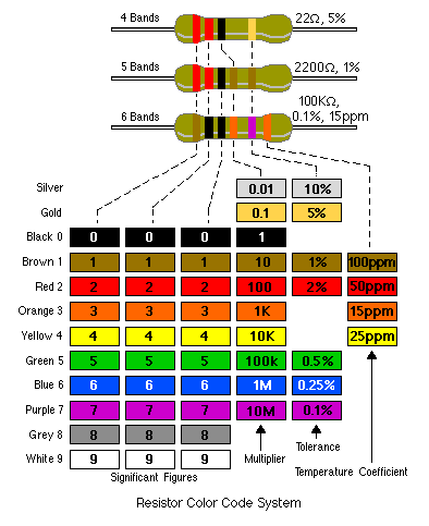
I found that this circuit board was harder then the first due to not completely understanding the components throughout it, once i worked out the resistors to use using the website, things went alot easier and ended up with a final result of a 5.17V output after tweaking a few things as my first test read 5.45V...to get it down to the 5.17V i had to change a resistor from a 220ohm to a 270ohm this is what got me into the le-way of 5V-5.19V.
If i was to remake this circuit board again I would make it more compact and tidy so that wires and components weren't crossing each other as this can cause shorting etc....

Circuit board 1

Components for this circuit board:

Resistor R1/R2 : 560 ohm's
Resistor R3/R4 : 1000 ohm's
2x 1.8v/20ma L.e.d's
2x c547w64 NPN transistors

With a Vs of 12v.
pwn : 5v


Calculations to finding out what type of resistors to use:

R1/R2 = (12v-1.8v/20ma) =10.2v/.020 = 510 ohm's

R3/R4 = 5-0.7/5ma
=4.3/0.005 = 860 ohm's

In this circuit we have the 12v power supply connected to the collector of the transistors, the 5v PWN signals which are low current flow through the base of the emitter, which then opens a the gate and allows the high current in the circuit to go through the collector then to the emitter, to ground.
To test if the circuit is working up to scratch a volt drop test can be done across the components of the circuit board
(You can Look up data sheets for all different types of transistors).....
I found Vce= 0.05V and Vbe= 0.08V. I also knew that the L.e.d's are 1.8volts.
Then i checked these 3 points with my multimeter and found that...

(Vce) was 0.04V for the two transistors.
(Vbe) was 0.84V= L.e.d 1 and 0.79V= L.e.d 2.
The voltage drop across L.e.d 1 was 1.84V, and L.e.d 2 was 2.12V.

In the end I think my experiment all went fine, the only real thing i could have changed would be to use less soldier for a cleaner looking circuit board, but it did what it was meant to do and everything functioned upto standard. For the first time making one the only down fall was putting one transistor in the wrong way but you learn from your mistakes so this could be expected from a first timer, all specifications were met without having to go back and change any major components though so am happy with end results.

Monday, August 16, 2010

Exp.8

If we are to increase the resistance at the base of the transistor it starts to shut off and the voltage drop increases quite rapidly at the collector and emitter or( Vce), When we increase the resistance at the base of the trasistor the current (ib) through the base is effected due to transistor working less efficiently, this will also effect the current flow in the collector and the emitter aswell.
The higher Rb is the lower lb is going to be, because there is a big amount of resistance there will be less current flow at the base of the transisitor.

Results below on table...

Tuesday, August 3, 2010

Exp.7 ...

V(be)= 0.8v

This is the voltage drop in-between the emitter and the base of a c547 type transistor, it shows that it has a knee voltage of just 0.8v

V(ce)= 0.05v

This is the voltage drop in-between the collector and the emitter, the voltage drop here is 0.05v this meaning the current is flowing freely from the collector to the emitter.

In the plot on the left the two regions labelled A and B represent two different things A being the saturated zone where the transistor is fully open and B being the "cut off" zone where no power can pass through working almost as a switch.

It takes O.7v for the transistor to be fully open(Saturated) and anything under that, is considered as the active zone where some flow is let through, but not none at all.

I had to calculate how much power is dissipated by this transistor at Vce of 3v using the graph above.
Calculations:

P=IxV
P=15x3
15exp-3x3 = 0.045ma
Power dissipation at 3v was (0.045ma)

I also had to find the Beta of this transistor at Vce 2,3 & 4 volts
Calculations:
Beta= IC/IB

2v: 20ma/0.8ma = 25
3v: 13ma/0.4ma = 32.5
4v: 5ma/0.2ma = 25


Monday, August 2, 2010

Transistor Exp.6

The image above shows the collector, base and emitter of normal PNP and NPN BJT Transistors, also showen is the construction of each transistor in terms of the P-type and N-type material layout within each component.


I had to test a PNP and NPN type of transistor 6 different ways with my multimeter leads. .

Results were:

This shows how the material in each of the transistors is effecting how the current can flow. mostly happening between the emitter and collector.

The Capacitor Exp.5

I had to calculate then test different types of resistors and capacitors to determine how long it takes for each to charge. I set the oscilloscope to a power supply of 1volt and each square representing 1 second each for easier reading.

My time calculations were:

1) 100exp - 6 = 0.0001x1000 = 0.1x5 = 0.5s x1000 = 500ms
2) 100exp - 6 = 0.0001x100 = 0.01x5 = 0.05s x1000 = 50ms
3) 100exp - 6 = 0.0001x470 = 0.47x5 = 0.235s x1000 = 235ms
4) 330exp - 6 = 0.00033x1000 = 0.33x5 = 1.65s x1000 = 1650ms

My observed times:

1) 750ms
2) 30ms
3) 300ms
4) 1720ms


I found that the higher the resistance in the circuit the longer the capacitor will take to charge due to the restricted flow of energy throughout the circuit.

(did not obtain oscilloscope pattern pictures)


Thursday, July 29, 2010

Experiment.4


I built this circuit on a breadboard using a 1k resistor, a 5v1 400mW Zener diode and a 1n4007 rectifier diode.


Vs =10v & 15v, R =1kohm ,1x zener diode ,1x rectifier diode.

Zd= 5.1v
d= 0.7v

I then had to test the voltage drop with my multimeter at each point around the circuit for both a 10v Vs and a 15v Vs these points tested being: Resistor, zener diode, rectifier diode and before zener diode to after rectifier diode..
Results..


Calculation for amp current:
10v: I=V/R=(10 - 5.1 - 0.7)1000= 4.2ma...

15v: I=V/R=(15 - 5.1 - 0.7)1000= 9.2ma...

Conclusion:

When the zener diode is placed in reverse bias it takes 5.1v just to start passing volt's through or to let it run...And a normal rectifier diode roughly 0.7v to let it run.
Therefore the voltage drop across the zener diode and the rectifier diode would be 5.8v (5.1+0.7=5.8v)
Voltage drop through the diodes will always stay the same, only if there was a power surge or too high voltage running through them-then they may be damaged.


Wednesday, July 28, 2010

Zener diodes Exp.3

I had to build a circuit on a breadboard containing two resistors of 100 ohm's and 1 5v1 400mW zener diode with a voltage supply of 12V.

The voltage drop through the zener diode was 5.1v , Working like a voltage regulator in the circuit.Whether you were too up the supply voltage to 15v or lower it to 10v the voltage drop would stay the same(5.1v) if you are using the same type of Zd. This circuit could be used to regulate voltage down to a suitable amount of volts you need, for what ever the components need.


R = 100ohms
RL = 100 ohms.
Vs = 12v , 10v , 15v.

Readings:

value of Vz = 4.94v
value of Vz = 4.69v
value of Vz = 5.07v

Then i reversed the polarity on the zener diode, which changed the value of Vz to .84v..this is the forward rated voltage drop of the diode.

Monday, July 26, 2010

Diodes Exp.2

First I had to identify which is the cathode (negative) and which is the anode (positive) on both Diodes and L.E.D's without using a multimeter..

To determine which is which on a diode, you can look up to the diode and see the one side which has a white strip, this is the cathode therefore the other side without anything just plain black is the anode.


To determine which is which on a L.E.D, look at the legs on the bottom of the L.E.D and you will see there is a longer leg and a shorter one, the longer one representing the anode and the shorter one representing the cathode or there is also a flat side on the bottom circle ring of the light which represents the cathode also..
Objective..
Next had to build a circuit board with a 5V power supply a 1k resistor and a 1N4007 diode on a breadboard.
First had to calculate the amount of current(amps) flowing through the the diode and then measure it with my multimeter to get an actual reading.
Results..
Calculation: 5V - 0.7V = 4.3V
4.3V/1000 ohm's = 0.0043a
or = 4.3ma
Measurement with multimeter:
= 4.5ma
I found that the Actual measurement was .2ma higher then my original calculations, maybe because resistance in the wires or not quite a perfect contact with the multimeter etc..
Objective..
Next had to calculate and measure the voltage drop across the diode on the same breadboard with the 5V power supply a 1k resistor and the 1N4007 diode.
Calculation: 4.3ma/1000 ohm's =4.3v
5v- 4.3v = 0.7v
Therefore voltage drop should be somewhere close to 0.7volts.
Measurement using a multimeter: 0.666v
This experiment worked out well and calculation to measurement was only slighty off to compare. (Picture up top left of me measuring circuit board with my multimeter for voltage drop).
Objective..
Next,had to replace the diode with a L.E.D(light emitting diode) and calculate then measure the circuit with my multimeter.
1.7v being the amount of power used to power the L.E.D..
Calculation: 5v-1.7v = 3.3v
3.3v/1000 ohm's = .33ma
Measurement using multimeter: .5ma

Sunday, July 25, 2010

Resistors Exp.1


Experiment 1. Determining resistance..

Objective.

Had to obtain 6 different resistors of different resistant values and calculate the value of each resistor by using a colour code chart using the maximum and minimum tolerance of each resistor, then measure each resistor value with our multimeters.

Results to experiment..


I then chose 2 resistors and then recorded there individual ohm resistances which i measured with my multi meter.

Resistor 1.. 990 ohm's

Resistor 2.. 2117 ohm's

Then we were required to connect the 2 resistors in series (joint end on end) and had to calculate the value in series (3107 ohm's) and then the actual test reading through a multimeter (3166 ohm's)

Next we had to connect them in parallel (both ends when they are side to side, end joint to end, almost joint like a circle) the calculated value was (3107 ohm's) and then again the measured recording through a multimeter was (.679 ohm's)

This experiment showed that the resistance when tested in series was added together to give you a joint resistance, where as when you test them in parallel you divide up the resistance because there is now 2 paths for the electricity to flow.